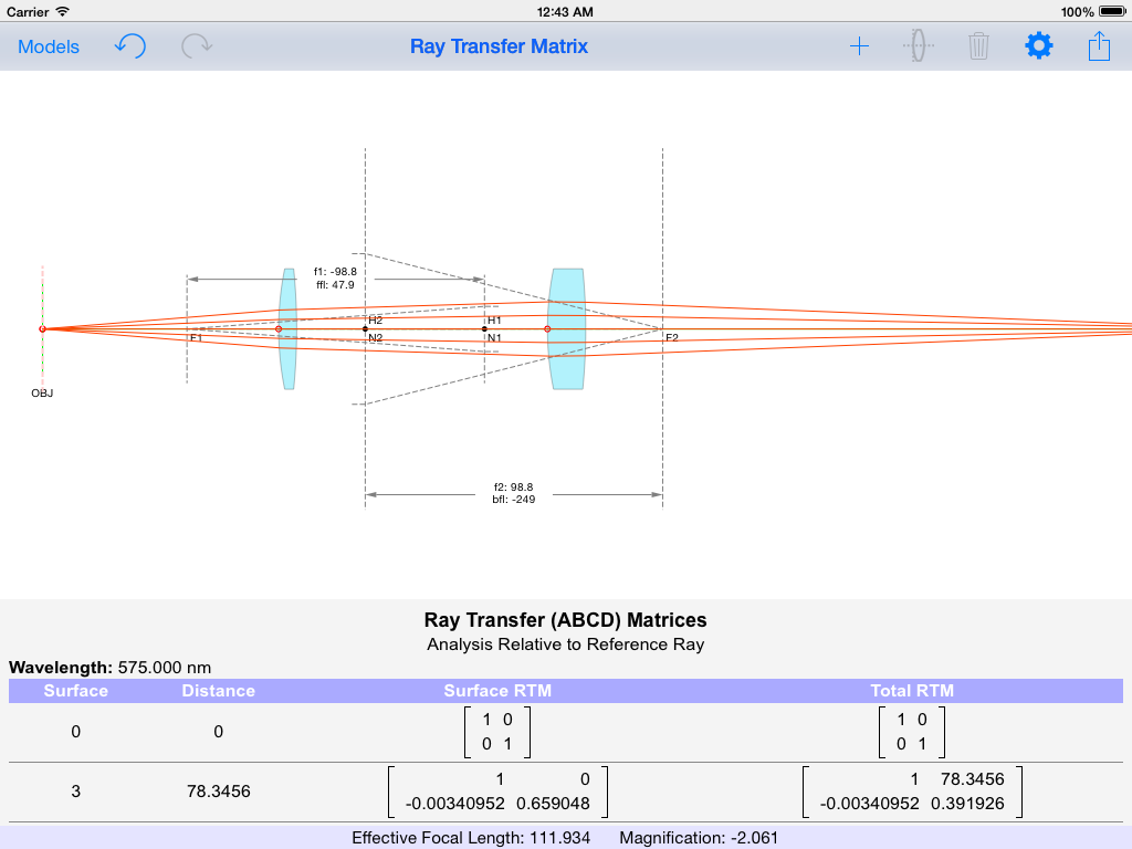
Ray Transfer Matrices allow representing multiple optical elements with a single matrix. This technique uses the paraxial approximation, which means rays are assumed to be at a small angle and a small offset from the optical axis. See general introduction to Ray Transfer Matrices on Wikipedia.
RayLab offers three analysis modes for computing Ray Transfer Matrices. These can be selected from the main model options menu.
All three modes use a reference ray leaving the object in order to determine the order in which optical surfaces are encountered. RayLab then computes the Ray Transfer Matrix by combining the RTMs for the encountered surfaces, as well as the RTMs representing their distances.
The 3 different analysis modes are as follows:
- Basic Axial Analysis: This approach uses a 2×2 matrix. It assumes all elements are on the z axis. Any tilt or decenter is ignored. Only the z coordinate of the surface vertices are used. This is the technique in most introductory descriptions of Ray Transfer Matrix analysis.
- Axial Analysis with Tilt/Decenter: This approach uses a 3×3 matrix. In addition to the usual ABCD elements, two additional elements, E and F, are used to account for tilt and decenter of the optical surfaces. The technique is valid for nearly axial systems with small tilt or decenter relative to the z axis.
- Analysis Relative to Reference Ray: This approach uses a 2×2 matrix as well. However, unlike the basic approach, ray offsets and angles are measured relative to the reference ray. This requires more sophisticated calculations for each surface to account for change in coordinate system. The technique is valid for analyzing a narrow pencil of rays which are close to the reference ray, even for non axial systems.
When performing Ray Transfer Matrix analysis, RayLab generates a report of all relevant matrices. It also uses the information to compute the cardinal points and surfaces for the system, and displays them in the main window.


Hello,
Is there anywhere a comprehensive manual for the app? I have tried to do simple things such as add a lens with a well defined focal length and I failed. Thanks in advance for the info
Clara
Hi Clara,
If you search for ‘Raylab kghandi’ on youtube you will find a couple of tutorials which I have uploaded.
Introduction: https://www.youtube.com/watch?v=nHQW8re7Ex4
Refraction: https://www.youtube.com/watch?v=xsCHOU-p9Ak
Gaussian Beams: https://www.youtube.com/watch?v=ZDe4GZupkBg
Raylab does not have a ‘focal length’ input for lenses. But it does have a ‘power’ input. So you can use the fact that lens power=1/focal length. Add a lens, choose first surface and edit the Glass type, Power, and Shape Factor. Shape Factor 0 is a symmetric lens, 1 or -1 are flat on one side and curved on the other.
Kamyar
Hello,
I am wondering, is it possible to get a short overview of the calculation method (formulas) used in Axial Analysis with Tilt/Decenter where you calculate the (E and F) when a tilt or a decenter is added.
I have gone through different books but couldn’t grasp the idea of how you are implementing it in your Matrix analysis. It would be really helpful if you could provide some insight.
Thanks in advance
Hi Zain,
The basic ABCD formulation is quite common and you can find many references for it including Wikipedia: Ray Transfer Matrix Analysis.
The case with Tilt/Decenter is only slightly more complicated. While I had seen the ABCDEF approach somewhere, I worked it out for myself when creating Raylab.
I can’t immediately find a reference which describes it now. I have not looked at the paper “Generalized beam matrices: Gaussian beam propagation in misaligned complex optical systems” by Anthony A. Tovar and Lee W. Casperson. But the abstract suggests it might provide the precise details of this approach. Note that the matrices used in Gaussian Beam Propagation are the same as the matrices used in Ray Transfer Analysis.
The basic idea is that in addition to (x2;u2) = [A B; C D] * (x1; u1) there can also be constant terms added by various optical components. We handle this by growing the matrix to include E, F, and adding a 1 at the end of the x,u vector… So:
(x2; u2; 1) = [A B E; C D F; 0 0 1] * (x1; u1; 1)
If something adds a slight offset to the ray, it will have an E term: [1 0 E; 0 1 0; 0 0 0]
If something adds a slight tilt to the ray, it will have an F term: [1 0 0; 0 1 F; 0 0 0]
To handle a standard optical element (say a lens) which is off-center, we combine several matrices:
1. Matrix to offset the ray by an amount corresponding to the off-center position of the lens.
2. Matrix for the lens.
3. Matrix to change back the offset.
In effect, this is changing reference frames… We start in our global frame, transition to the lens frame, apply the lens matrix, and transition back to the global frame.
You do something similar for tilt.
The 3rd option in Raylab for Ray Transfer Matrix Relative to a Reference Ray is much more complicated. My reference for this was “Ray Techniques in Electromagnetics” by George A. Deschamps. Particularly section III.A. “Tracing of a Pencil” which culminates in equations 42-45. The notation in this paper was quite different than what I was familiar with. So I followed his approach while rederiving the equations in notation I could understand and relate to Raylab. The final result involves the angle of incidence and local curvature of the surface at the point where the reference ray hits it.
With all of these approaches, you also have to pay attention to some signs getting flipped when you encounter mirrors and when rays are traveling backward.
Hope this helps.
Kamyar
Do you have any simple tips for replicating a refector telescope